Description
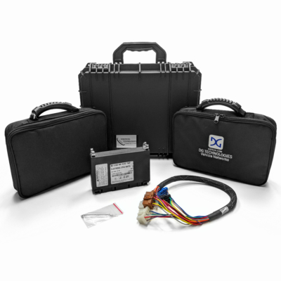
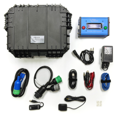
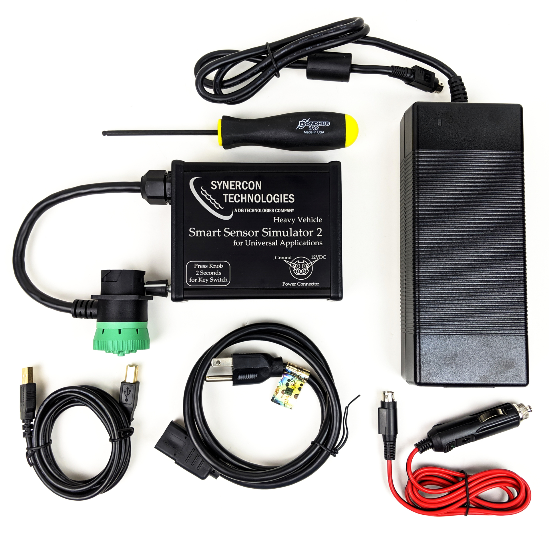
Kit Contents:
- SSS2 Unit
- AC Power Supply
- 12V DC Car Power Supply
- USB Cable
- 5/32″ Hex Driver (Required for some ECM connectors)
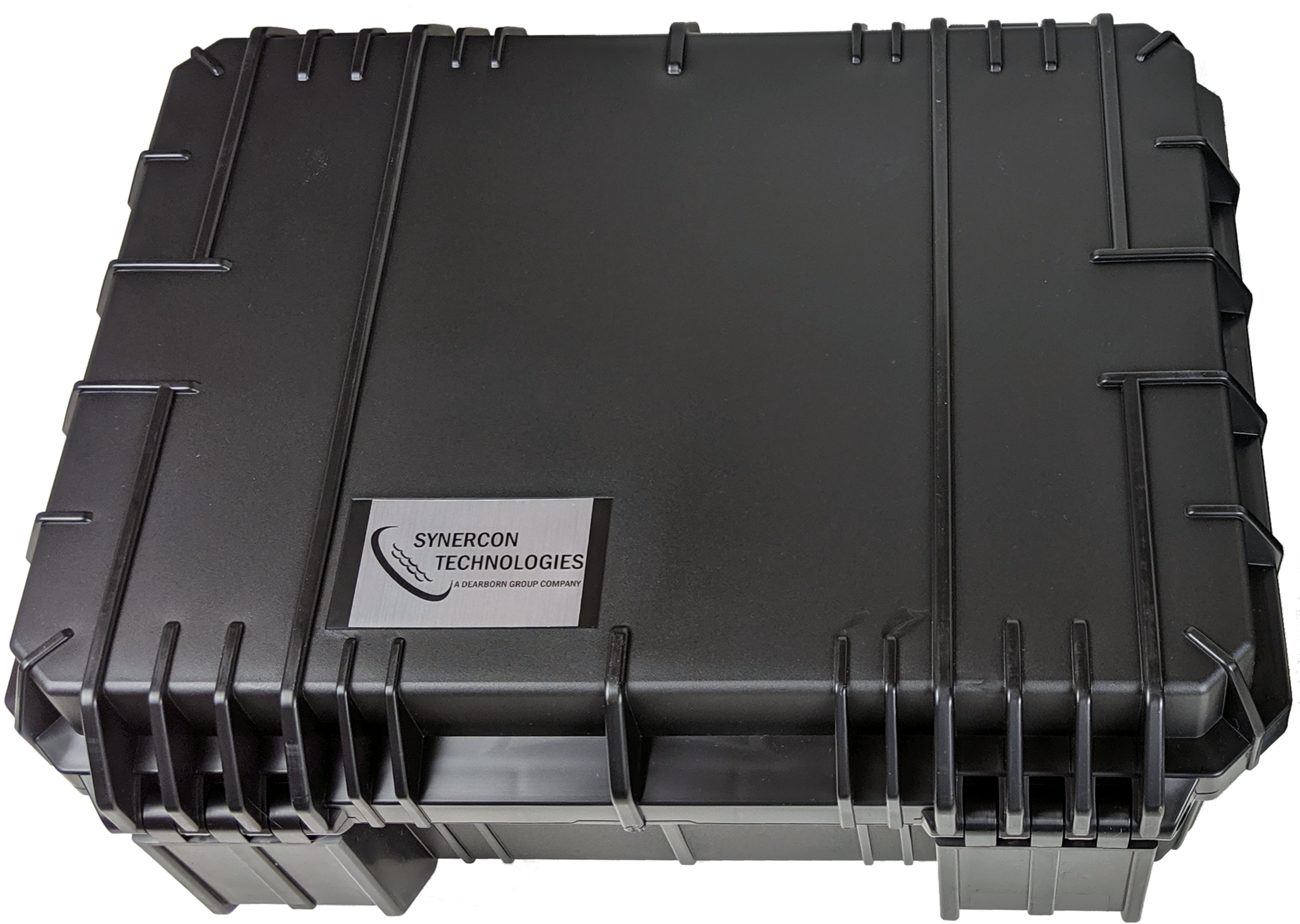
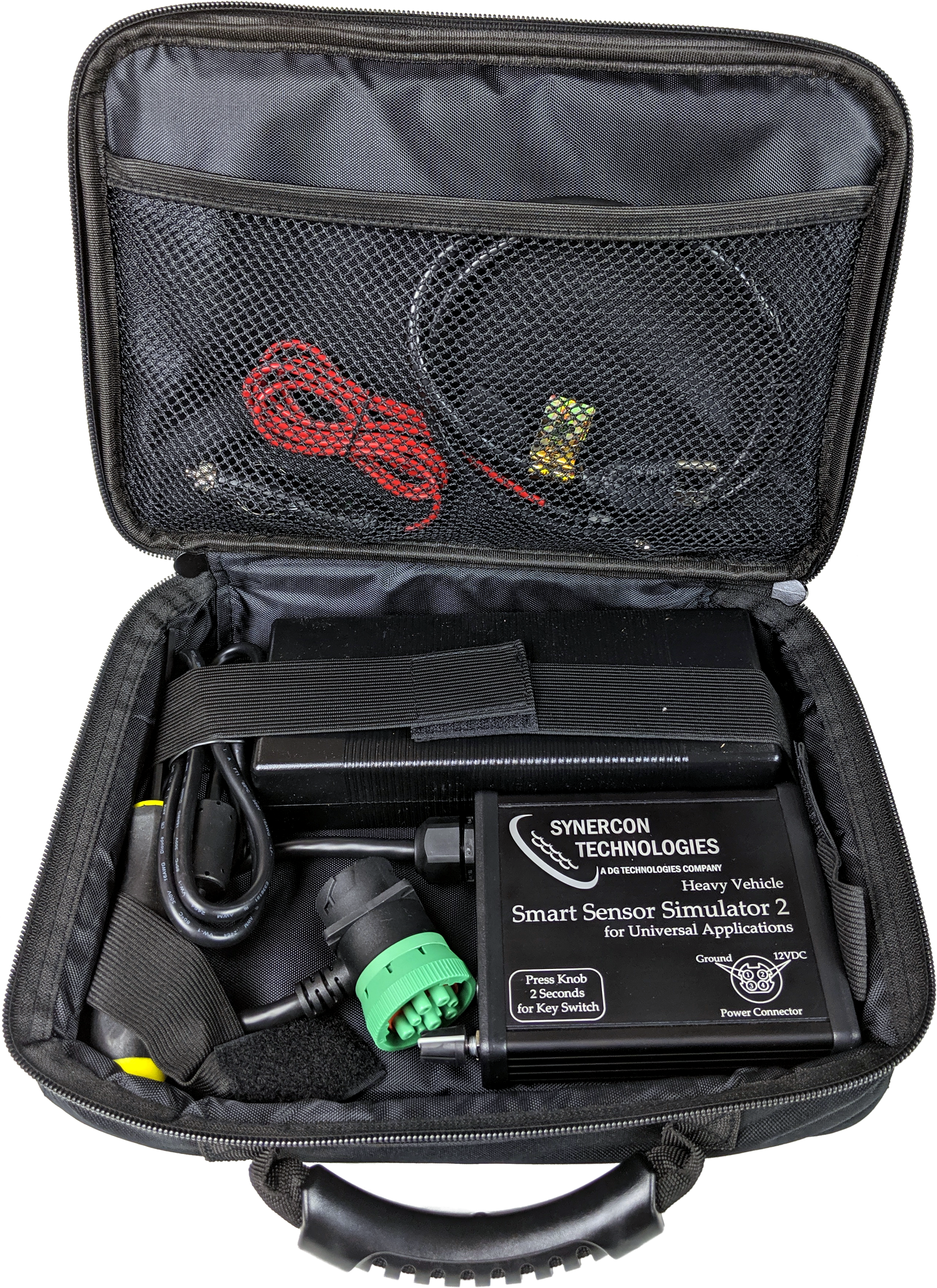
- Rugged Carrying Case (SE-630)
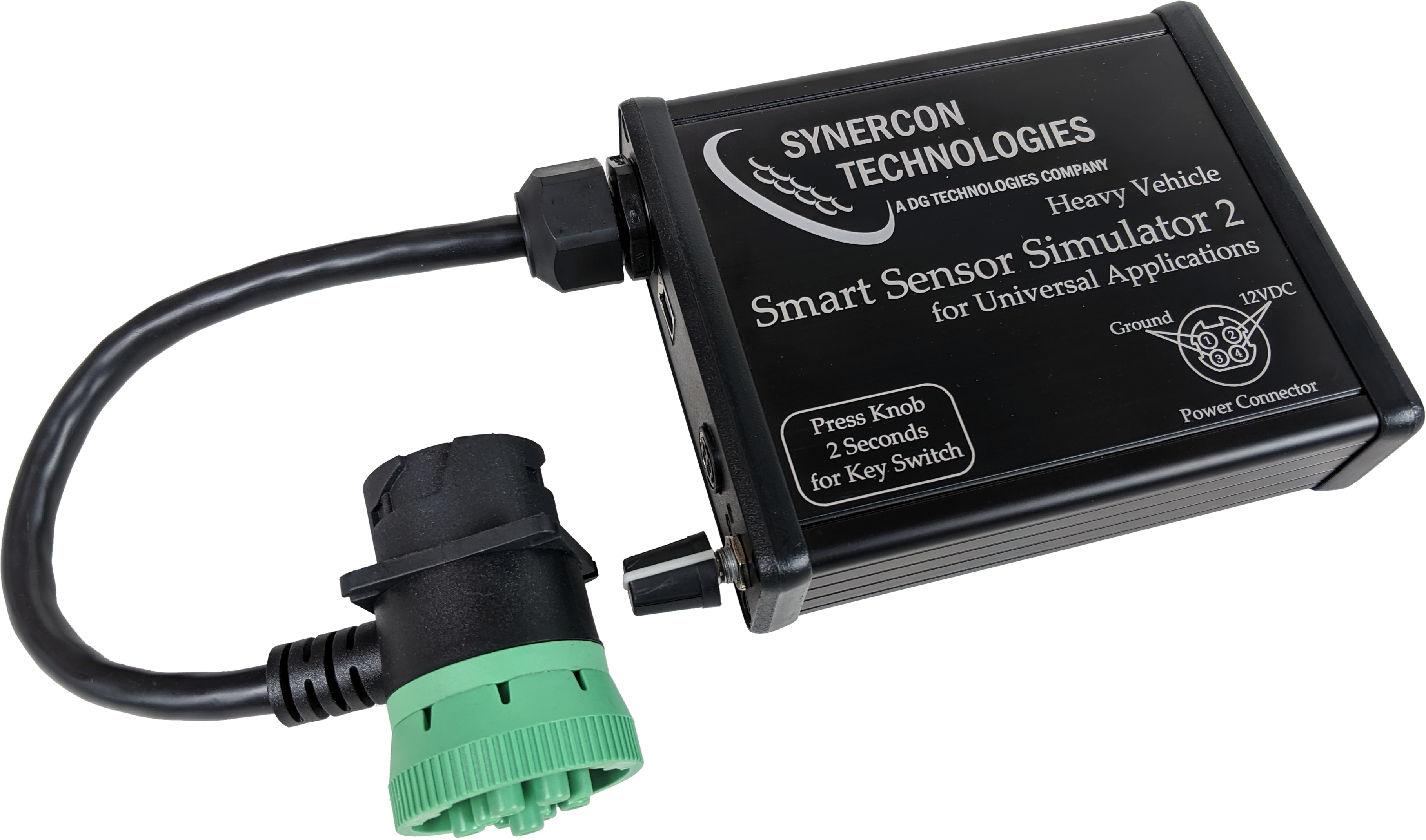
End Panel Description:

Male/Female 9-pin Deutsch Connector
USB interface cable to communicate with a PC
+12VDC IN
Power Indicator. If J1939 network traffic is present, this LED will flicker at a rate reflecting the J1939 busload
Key Switch Indicator. If J1708 or CAN traffic is present, this LED will flicker
User Input Knob. Press knob for 2 seconds to cycle the key switch relay.
Definitions and Capabilities:
CAN – Controller Area Network up to 1M bits/sec
LIN – Local Interconnect Network. This is programmed to simulate the shifter lever on Freightliners with an automated transmission.
PWM – Pulse Width Modulated with adjustable frequency and duty cycle. These are 0 to 5V square wave signals.
Digital Potentiometers
The digital potentiometers are 12V tolerant devices with independent terminal connection control. A potentiometer has three terminals: Terminal A, the Wiper, and Terminal B connected to ground. The potentiometer is rated to have a resistance from Terminal A to Terminal B. The wiper picks off from along the resistor string. The terminals can be configured to open and close independently. This gives you the ability to connect the potentiometer as a voltage divider, resistance to ground, or resistance to a high source. The terminals are connected by selecting the checkboxes on the SSS Interface under the Digital Potentiometers tab.
Digital potentiometers can simulate signals that are used for
- Temperature Sensors
- Pressure Sensors
- Analog Accelerator Pedals
- Actuator Presence (i.e. the presence of an actuator)
The digital potentiometers used in the SSS2 are the MCP41HV51 and MCP45HV51. The digital potentiometers have a limit such that the wiper plus the terminal is between 250 to 300 ohms.
Analog Output
Analog outputs generate signals from 0 to 5 V. The signal is generated by a Digital to Analog Converter (TI DAC7678) and buffered with an op-amp. Each signal is capable of sourcing 25 mA. 
Analog Outputs can simulate signals for:
- Pressure Sensors
- Switches to ground (by setting the output voltage to 0)
Analog outputs are similar to a voltage divider when examining the signal with a meter. However, voltage dividers based on a potentiometer sink current and analog outputs can both sink and source current.
Cable connections for the SSS2
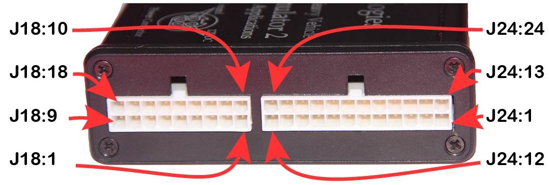
24 Pin Molex Connector:
- Digital Potentiometer (10k) or PWM5*
- Digital Potentiometer (10k) or PWM6*
- Digital Potentiometer (10k) or CAN1L*
- Digital Potentiometer (10k) or CAN1H*
- Digital Potentiometer (10k)
- Digital Potentiometer (100k)
- Digital Potentiometer (100k)
- Digital Potentiometer (100k)
- Digital Potentiometer (10k)
- Digital Potentiometer (100k) or Analog Out B
- Digital Potentiometer (10k) or +12V Output
- Digital Potentiometer (100k) or Ground Output
- Digital Potentiometer (10k) or PWM1
- Digital Potentiometer (100k) or PWM2
- Digital Potentiometer (10k) or Analog Out A*
- Digital Potentiometer (100k) or LIN
- CAN2L or J1708-
- CAN2H or J1708+
- High Current Regulator Adjustable Output
- Ignition Switch (+12V Relay)
- J1939H
- J1939L
- +12V Output (protected)
- Ground
18 Pin Molex Connector:
Cable connector is Molex part number 39-01-2180.
- Ground Out or PWM4
- Analog Out – A
- Analog Out – B
- Analog Out – C
- Analog Out – D
- Analog Out – E
- Analog Out – F
- Analog Out – G
- Analog Out – H
- +12V Output or PWM3
- High Current Regulator Adjustable Output
- Digital Potentiometer or PWM4*
- Digital Potentiometer
- Digital Potentiometer
- CAN2L or PWM1
- CAN2H or PWM2
- Battery + Input (unprotected)
- Ground
*Only on Hardware Revision 5 and up.
Pulse Width Modulated Output
Pulse width modulated outputs are square waves from zero to +5V that have an adjustable frequency and duty cycle. These signals can be used to simulate analog values by adjusting the duty cycle. In other words, a voltmeter will read between 0 and 5v based on the duty cycle. A duty cycle of 0 means the output is driven to ground through an op-amp. A 100% duty cycle means the signal is always on at +5v. The frequency can be set from 0 to 5000 Hz. 
Pulse width modulated signals are the only way to simulate throttle position sensors for some ECUs, like Caterpillar and PACCAR MX.
These signals can also be used to generate speed signals for researching event data recorder capabilities.
Not all channels have independent frequency settings. The PWM1 and PWM2 signals have a common frequency that can only go as low as 245 Hz. PWM3 and PWM4 share the same frequency. PWM5 and PWM6 share the same frequency. The output of PWM 3 shares the pinout for a switched +12V supply and has a 10uF capacitor to ground. This capacitor acts like a low-pass filter, so high frequency values on PWM3 tend to be averaged out and do not show the switching behavior of the other PWM signals.
Smart Sensor Simulator Interface
A Graphical User Interface (GUI) to set configurations for the SSS2 to accommodate different ECUs for the entire fleet. This enables you to have just one Smart Sensor Simulator 2 for all your electronic control unit interface needs.

Current Release:
SetupSSS2Interface-1.0.8.zip (Try this in case your computer restricts downloading executable files.)
This installer includes a serial driver to communicate with SSS2 from Windows 7 and 8. Windows 10 should already have the driver installed. You may need administrator privileges.
The latest set of SSS2 settings files come bundled with the executable and are also available as a .zip file.
See Release Notes for previous releases, bug fixes, and new features.
Click here for additional information on using the Interface Application.