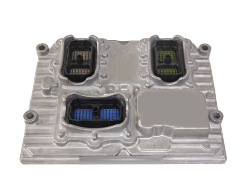
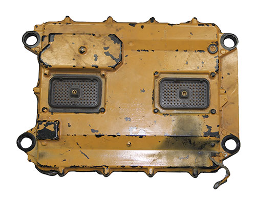
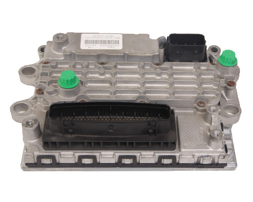
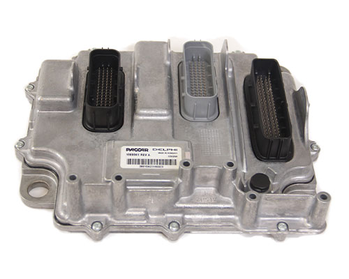
The Smart Sensor Simulator is a device that emulates an entire truck for an ECM.
_______________
The Smart Sensor Simulators (SSSs) are devices that emulate the electronic systems of a truck. This “truck-in-a-box” technology enables investigators to retrieve electronic control modules (ECMs) from damaged vehicles and perform a forensically sound bench-top download. The SSS can provide a fault-free environment for a forensically neutral download of the data contained in an ECM. The SSS reduces the chance of setting new fault codes and overwriting valuable digital forensic data that may be related to a crash.
Production of the Smart Sensor Simulator has ended. Please look into the Smart Sensor Simulator 2 for greater functionality and performance.
Cummins
- SSS-CM850
- SSS-CM870
- SSS-CM871
- SSS-CM2150
- SSS-CM2250
Detroit Diesel & Mercedes
- SSS-DDEC4
- SSS-DDEC5
- SSS-DDEC6
- SSS-DDEC10
- SSS-DDEC13
- SSS-MBE
PACCAR
- MX-11/13
NAVISTAR
- MaxxForce
Smart Sensor Simulator Theory of Operation
The Smart Sensor Simulator (SSS) is a device design to:
- Enable benchtop downloads of heavy vehicle electronic control units (ECUs).
- Produce a fault-free or reduced fault environment to better preserve the digital record stored in an ECU.
The SSS has circuits and devices to emulate the sensors and network traffic of a heavy vehicle. By generating these signals, an engine control module (ECM) can be powered on without setting new fault codes. Sometimes data on heavy vehicle ECMs can be downloaded as part of a crash investigation. Obtaining and preserving this data is important in a forensic context. When an ECM is turned on to download, the data associated with a fault code may be overwritten if new faults are detected.
Design Requirements and Goals
The design goals of the Smart Sensor Simulator is to be a cost effective solution to communicating with heavy vehicle ECMs while being able to adjust the simulated outputs. The types of signals that are needed to be generated are as follows:
- Switches to Ground
- Resistors to Ground
- Resistors to +5V
- Resistors to +12V
- Analog voltage signals
- Resistors between two ports
- Pulse width modulated (PWM) signals
- Frequency Modulated signals (Hall Effect emulation)
- Controller Area Network signals to produce J1939 messages
- Ignition key signal
Smart Sensor Simulator Components
With the Smart Sensor Simulator internal hardware being the same, SSS models are distinguished by the interface cables and the software. There are three primary component that are assembled into an SSS.
- Common hardware and printed circuit board (PCB)
- Specific cable interfaces to connect an ECM model to the common PCB
- Software that can run on the different microprocessors on the PCB to configure the PCB to provide the correct signals for specific ECMs
For more detailed information please contact us.


