Using the Smart Sensor Simulator 2 Interface Application
Details and tips on how to use the settings files with the Smart Sensor Simulator 2 for maximum benefit. The Interface App is free of charge.
Downloading and Installing
The SSS2 Interface App is written for Windows and is tested on Windows 7 and 10. You can download the latest version of the Interface App from the Smart Sensor Simulator 2 product page.
Once downloaded, you can run the executable to install it. Some computers will not recognize the application and ask you to block it. If this happens, you may need to override those settings. For example, on Windows 10 with the Windows Defender, a blue box may come up saying “Windows protected your PC.” If this happens, then press on the link that says More info. From there you can press Run Anyway.
The install process will install the Application and its support files. It will also create a new directory in your documents called SSS2. This new directory will contain all the SSS2 settings files. Finally, the virtual serial driver will be installed. On Windows 10, this step is skipped because the drivers are native to the operating system.
SSS2 Interface App Settings Files
The settings files for the SSS2 enable a user to adapt the settings of the SSS2 for a particular application and save them. The files are unique for each SSS2 and cannot be shared. However, there are a set of files available for download that will work with any SSS2. The SSS2 Interface Application requires an SSS2 to be plugged in to save and load files. The Interface App save a unique ID from the SSS2 into each file. Also, the file contents and settings are periodically hashed, so the system can tell if the contents of the settings have changed. Each time the settings file gets saved, a new hash is calculated and saved. This helps users know if their files or settings have been changed.
Download the ZIP archive of Settings Files (*.SSS2)
The files in the ZIP archive contain the tested settings for the SSS2. Keep in mind that not all settings files produced a fault free condition for the tested ECU. Check each individual file for the test conditions and results.
Plugging In the SSS2
A power source must be plugged into the SSS2 using the a +12V supply. The internal USB power is not connected to the microprocessor inside the SSS2. The order of plugging in the USB and Power for the SSS2 does not matter. However, if there are issues with the serial connection, it is best to cycle power to the SSS2 instead of unplugging and replugging in the USB cable.
The order of opening the SSS2 Interface App and plugging in the USB does not matter. The SSS2 Interface app is programmed to detect the last SSS2 it was plugged into. If the USB connection is present, then it will automatically connect.
The SSS2 uses a serial over USB connection to interface with the SSS2 unit. This means the SSS2 shows up as a COM port in the Windows Device Manager. On Windows 10, you can open the device manager by clicking the start menu and start typing “device manager” without quotes.
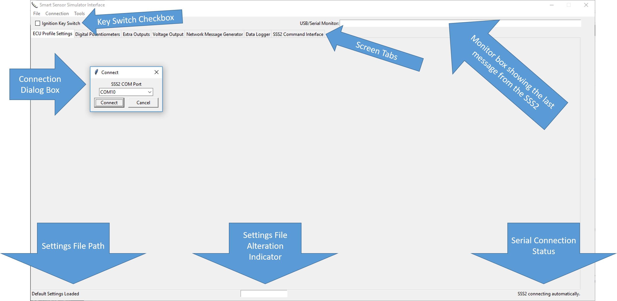
Successful connection between the SSS2 and the Interface App is indicated by seeing the FIRMWARE version in the upper right hand entry box shortly after connection. If the USB/Serial Monitor box is red, then there is no communication between the App and the SSS2.

Selecting a COM Port
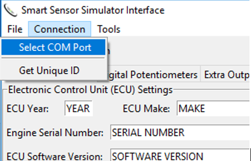
To select a COM port, select the menu item in the Connection menu. The dialog box to connect to the SSS2 automatically refreshes with possible COM ports that would have the SSS2 attached. Usually, the highest number COM port is the correct one, which is selected by default. However, you can select other COM ports. If the refresh takes place, which is every 4 seconds or so, then the select COM port will be changed back to the default. If this happens, try selecting the desired port again and press OK before the refresh takes place. You can tell if the SSS2 is connected to the COM port in the dialog box if you unplug the USB cable and the COM port number goes away. You may have to cycle power on the SSS2 to reset it and clear the red box.
SSS2 Interface Tabs and Layout
This section describes each of the tabs and how to use them. The details on the operation of the SSS2 Interface App will help the user understand how the system works.
Initial Screen
When the SSS2 Interface Application is started and it cannot find an SSS2, the following screen will show up with a dialog box asking for the COM port for the SSS2. Once the SSS2 is connected through a COM port, the SSS2 Interface App will remember the COM port and the port selection dialog will be automatically bypassed on startup. If a different COM port is needed, then it can be selected through the Connection menu.
ECU Profile Settings Tab
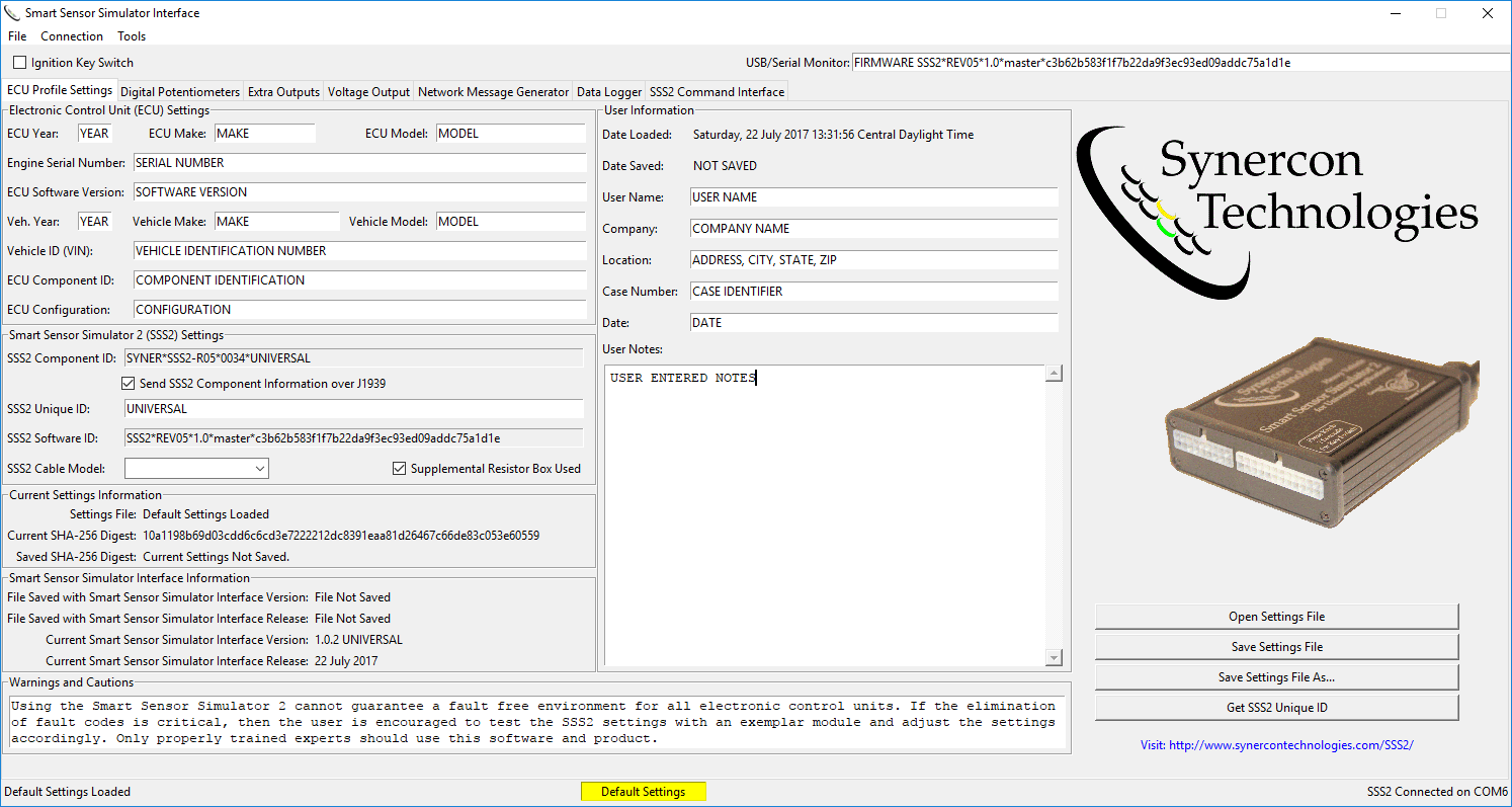
This tab is made up of 6 distinct areas. Each area is boxed with a descriptive title. On the lower right corner are common menu functions that are displayed as buttons.
Electronic Control Unit (ECU) Settings
This area is for the user to enter meta data related to the ECU under study. These fields must be manually entered but the user. Not all modules will have all the information, but the template provides some ideas on pieces of information to gather. These values are included in the hash calculation, so any modification will be detected. The data in this box should help ensure the correct application of the settings file.
Smart Sensor Simulator 2 (SSS2) Settings
This area contains information related to the SSS2 configuration. The first box is for the SSS2 Component ID. This field follows the J1939 format for component ID with a Make * Model * Serial Number * Unit number format. The Make is always SYNER for Synercon Technologies. The model will start with SSS2 then have the hardware revision number (e.g. R05 for the revision 5 hardware). The Unit number field is always filled with the word UNIVERSAL. Since this format follows J1939, the SSS2 can broadcast that component ID over the network if the checkbox is selected. By default, the SSS2 Component ID is broadcast over J1939 every 5 seconds.
 The Unique ID comes from the microprocessor itself and is pre-programmed at the factory. When files are opened, the file must have the correct unique ID, or the word UNIVERSAL in the SSS2 Unique ID field. This is a user entry field, but the Unique ID should be populated using the Get SSS2 Unique ID button in the lower right of the tab. This must be done before the settings file can be saved.
The SSS2 Software ID indicates what version of the firmware is running on the SSS2. The firmware is delimited by an asterisk into the following fields: Model * Hardware Revision * Release Number * description * git hash. The git hash reflects the commit hash for the open source firmware running on the SSS2. Advanced users can use the Arduino and Teensyduino software environments to adapt the SSS2 for custom applications. The source code that includes the hardware schematics are available on Github: https://github.com/jeremy-daily/SSS2.
The cable model is user entered (i.e. it is not automatically set) to indicate which cable system was used for the application. Occasionally a supplemental resistor box is needed to simulate all the different sensors used by an ECU. If this is the case, a checkbox is provided to remind the user to install that resistor box on the cable.
Current Settings Information
The first line of this informational block show the current settings file name. This is a short version of the full path file name shown in the bottom left corner of the window. The second and third lines show the cryptographic hash result of the settings. The Current SHA-256 Digest is calculated frequently and looks for changes against the saved SHA-256 Digest. If the two digests match, then the indicator box at the bottom middle of the window will show a green box that says Settings Unchanged. If the any changes are made, a new hash value is calculated and willbe different than the saved version. When this happens, the indicator box at the bottom middle of the window will show a red box that says Settings Altered. Upon startup, there are no settings files loaded, so the indicator box is yellow indicating the default settings are in the system and the settings are not saved. Since there is no new settings file for comparison, the box will stay yellow until the settings are saved.
Smart Sensor Simulator Interface Information
The information in this area show the interface application version information for both the settings file and the application itself. This helps users know they are using up-to-date settings files.
Warnings and Cautions
Using the Smart Sensor Simulator 2 cannot guarantee a fault free environment for all electronic control units. If the elimination of fault codes is critical, then the user is encouraged to test the SSS2 settings with an exemplar module and adjust the settings accordingly. Only properly trained experts should use this software and product.
This warning is built into each SSS2 file and cannot be changed. To become a properly trained expert, it is encouraged that you attend a class that teaches about the SSS2 and heavy vehicle networking. Many settings that are required for fault free systems are based on network traffic, thus understanding J1939 and CAN is important to making effective settings changes. Synercon Technologies will continue to provide files for exemplar modules. These file are generated one at a time and for specific ECUs.
User Information
The fields in this area are user entered information. The data is optional, but can be useful in building a case file. User Notes give an free form text box to explain details about the ECU or the case. The data in these fields are tracked by the SHA calculator, so changes in these fields will be reflected in the indicator box at the bottom middle of the window.
Digital Potentiometers Tab
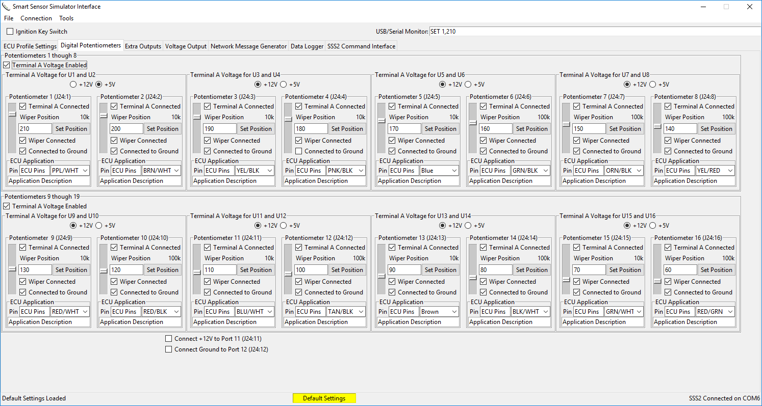
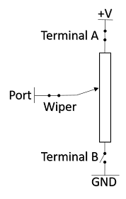
This tab controls 16 digital potentiometers. These potentiometers are configurable and can simulate a number of sensors. There is a hierarchy to the organization of the potentiometer controls in this tab. At the highest level, there are two rows: Potentiometers 1-8 and Potentiometers 9-16. These banks are separated into four pairs of potentiometers, with each pair connected by Terminal A. The voltage supplied at terminal A can be either 5V or 12 V selected per pair. However, the voltage sources can be disabled for each bank of eight potentiometers, in which case none of the eight potentiometers would have an external voltage.
Potentiometers have a versatile application in simulating sensors. In the next section, we will explain these strategies using schematic symbols, SSS2 Interface Settings, and an application description.
Application Description
Schematic Symbol
SSS2 Interface App Example Settings
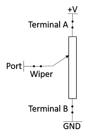
Voltage Divider
A voltage divider provides a reference voltage at the terminal of the potentiometer by adjusting the wiper between the high and low terminals. There are 256 different positions for the wiper terminal on the digital potentiometer. This strategy can simulate most “three wire” sensors, like pressure sensors. Connecting a multimeter to the output pins of the potentiometer and moving the slider with all the terminals connected can show how the voltage divider works.
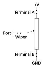
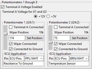
Resistor to Ground
A variable resistor is also known as a rheostat. If the top terminal (Terminal A) is disconnected, then the circuit acts like a variable resistor to ground. This is common for temperature sensors used on vehicles and they are known as thermistors. The variability of resistance due to temperature is easily simulated using the SSS2’s digital potentiometers. When the wiper is set to zero, the terminal resistance is about 260 ohms. The maximum resistance is estimated by the total resistor value indicated next to the wiper position. The SSS2 digital potentiometers are either 10k or 100k ohms.
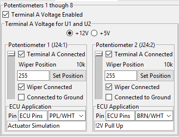
Pull-up Resistor
Some actuators on vehicles are driven by low-side drivers, which means the actuator is connected to a 12V source and the actuator is enables by completing connecting the actuator to ground. Therefore, the ECU will look for the presence of +12V to ensure the actuator is connected. To do this, we can provide a resistance of greater than 260 ohms to a battery supply source. Keep in mind that some actuators use coils that are 10 ohms or less, so if an ECU tries to fire the actuator and looks for the high current, the SSS2 will not provide that condition.
Port to Port Resistance
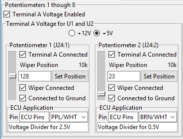
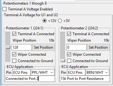
Some sensors, like a vehicle speed sensor (VSS) are simulated by a resistor between both ports. To simulate this with the SSS2, we have to use 2 ports next to each other. The pairs of potentiometers are tied together using their top terminal. This means we can disconnect the ground terminals and have a resistor that is the equivalent of adding the resistance of both potentiometers from the wiper to terminal A. In the example shown, potentiometer 1 is set about half way, which gives it a resistance from the port to terminal A of about 5k. Potentiometer 2 is using the full resistance of the potentiometer of 10k to go from Terminal A to the wiper. Therefore, the total resistance from Port 1 to Port 2 (i.e. the simulated sensor) is 15k ohms. This strategy may require that the Terminal A voltage is disabled. This means that Potentiometers 3 though 8 have to follow the same pattern of Port to Port Resistance or a resistor to ground. In other words, this mode will disable the potentiometers to act as a voltage divider.
Many external pins on the SSS2 have multiple functions. On the Digital Potentiometers tab, there are check boxes to enable high current pins on Port 11 and Port 12. Port 11 can provide a low resistance path to a +12V source and Port 12 can provide another low resistance connection to ground. These paths to power are through a dedicated H-Bridge driver that is typically used to drive motors with high current. Many times it is convenient to have additional power rails for turning on ECUs.
Extra Outputs Tab
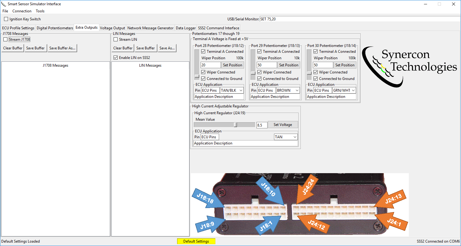
The Extra Outputs tab was named because it has some of the extra parts that did not fit on other tabs. There are 3 more digital potentiometers, a high current adjustable voltage regulator, the J1708 monitor and the LIN monitor.
Digital Potentiometers
The three additional potentiometers are connected by default to be voltage dividers with the top terminal (Terminal A) to be at 5V. The different terminals can be opened or closed to make it a pull-up resistor, pull-down resistor, or disconnect the port altogether. The top terminals are not connected, so each of these potentiometers is independent. A good application for the 100k potentiometers would be to simulate temperature sensors.
High Current Adjustable Regulator
The high current regulator can source up to 5 amps of current from 1.9V to 11.0V. This feature enables the ability to power on equipment with low power or maintain a reference voltage. An example of this utility is when turning on a Bendix Brake controller with around 8.5 V, the system recognizes a low voltage condition and stops looking for additional fault codes. However, communications are still enabled, which means the digital record on the device is accessible and new faults have not been found due to the low voltage condition. There may be other modules that have similar behavior.
This regulator can also emulate voltage producing sensors when the voltage output is pushed to the lower level.
WARNING: This regulator is a linear regulator, which means it will generate heat. Please monitor the system closely for excess heat if using this regulator for long a duration with high current.
J1708 Messages
The J1708 message area has a checkbox to stream or display J1708 messages that are coming though the SSS2. These messages are not interpreted, but they can be logged. The presence of messages means communications are successful. The data in the buffer can be saved as a comma separated values file (CSV) for further analysis. The data in the display is in hexadecimal format. The leading characters are the message identifier (MID). Common MIDs are 0x80 for an engine and 0x88 for a brake controller.
LIN Messages
Local Interconnect Network (LIN) is used for vehicle electronics communication. It is designed to be low cost and reliable. The SSS2 implements LIN to simulate the shifter lever for Freightliner trucks that have an automated transmission. The shifter lever is mounted on the right side of the steering column and provides the Common Powertrain Controller (CPC4) messages that indicate the driver’s desire, like Drive, Neutral, Reverse and so forth.
LIN requires a master device to communicate. The master device for the SSS2 is intended to be the CPC4. The master device (CPC4) will send out three bytes to communicate: 0x20, 0x55 and 0x14. The slave device (SSS2) will then respond with the data bytes, a counter, and checksum. These data show up in the LIN Messages box and can be saved to a CSV file for further analysis. The LIN data is in hexadecimal format.
The LIN capabilities are designed only for the CPC4, but the source code could be modified to accommodate other LIN transactions, if necessary. This feature eliminates a DDEC fault code related to LIN communications.
The LIN communication engine on the SSS2 can be turned off by deselecting the checkbox. The LIN output is enabled on Port 16 and/or Pin E of the 9-pin connector by selecting the appropriate checkboxes on the lower right corner of the Network Message Generator tab. The LIN master pullup resistor does not matter when using the CPC4, since the CPC4 already has the pullup resistor.
Voltage Output Tab
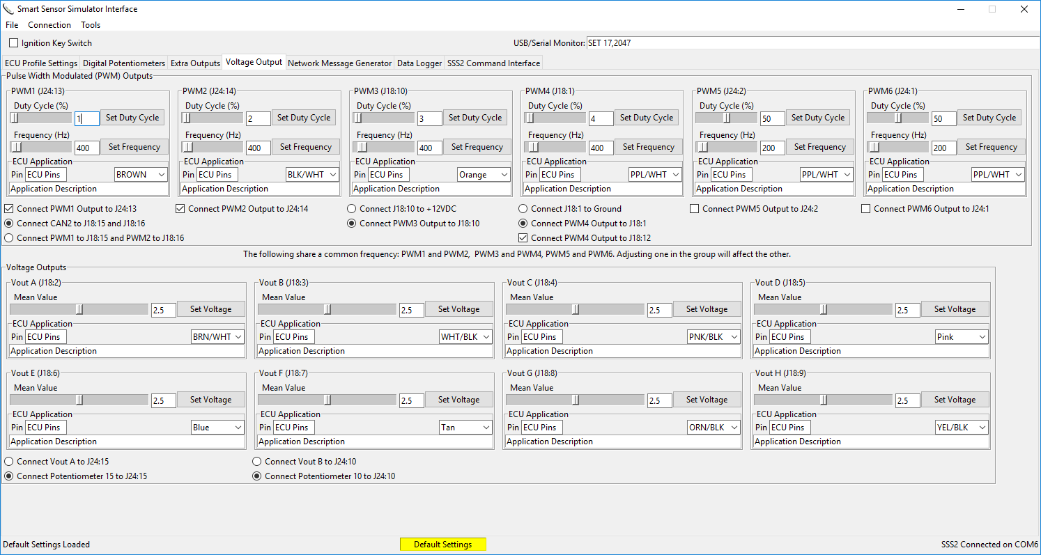
This tab controls analog voltage outputs, pulse width modulated outputs, and controls many of the different options for output pins. These signals are useful for simulating accelerator pedal position sensors, pressures, or other voltage reference signals. All of these voltages have a maximum of 5V, but can also be driven to ground though a nominal resistance of 60 to 80 ohms.
There are two areas in this tab. One for Pulse Width Modulated (PWM) signals and the other for plain voltage outputs.
Pulse Width Modulated Signal Basics
A PWM signal is generated by switching a voltage level on and off. The amount of time the signal is on compared to the period of the signal is called the duty cycle. The duty cycle can vary from 0%, which means the signal is always grounded, to 100%, which means its always on. A 50% duty cycle means the time the voltage is present matches the time at ground. The duty cycle drives the equivalent DC voltage. If a multimeter is connected to a 5V PWM waveform at 50% duty cycle, it will read 2.5V. Similarly, if the duty cycle is at 20% (1/5), then the voltage will be 1 volt.
The rate at which the switching happens is called the frequency. Higher frequency switching make the perception of the PWM to seem more like a constant voltage. This is a common strategy for “analog voltage” outputs from microprocessors and is used frequently for controlling light and LED brightness. The frequency is determined by a clocksource within the microprocessor, and some of the different channels share the same clock source. This means adjusting the frequency of one affects the frequency of another.
Pulse Width Modulated (PWM) Outputs
All PWM signals can go from 0 to 100% duty cycle independently. Most of the time, a 50% duty cycle will be sufficient. You can use PWMs to simulate sensors that provide speeds, like vehicle speed, fan speed, or engine speed. Doing this, however, can potentially create new speed records on the subject module, so this feature is used for research and understanding.
Do not connect a PWM signal to a the Vehicle Speed Sensor or Engine Speed Sensor if you are doing a forensic examination of an ECU.
The lowest frequency for PWM1 and PWM2 is 245Hz. This may pose an issue for simulating sensors like accelerator pedals because some accelerator pedals are expecting a 200Hz signal. PWM3 though PWM6 can have low frequency switching (i.e. down to 1 Hz). The highest frequency for the slider is set to 5000 Hz. If a higher frequency is desired, you can manually enter it into the Command line of the SSS2 Command Interface. For example, if a 32kHz signal is needed on PWM5, you could enter “85,32000” (without quotes) into the command box and press enter. This would generate that frequency for you. As an aside, you can stream frequencies using the same serial commands to continuously adjust the frequency to simulate running conditions. The highest frequency accepted by a Serial command is 65535 Hz.
Many pins on the SSS2 have multiple purposes and can be configured to operate in different ways. This is commonly called pin multiplexing, or pin muxing. There are a series of radio buttons and checkboxes that enable different pin configurations. For example, PWM1 is normally not connected to J24:13. Instead, J24:13 is a digital potentiometer. When the checkbox is selected, the SSS2 switches pin J24:13 to the PWM1 signal.
One multiplexed signal is a +12V switched power rail to J18:10 that shares a pin with PWM3. Because this pin is a power rail, there is a 10uF capacitor between J18:10 and ground. This capacitor has the effect of smoothing a signal as frequencies get higher. As a result, the PWM3 signal is not a square wave, instead, it rounds the corners off with an exponential curve. For PWM3 frequencies up to about 200 Hz, the signal has a peak-to-peak voltage of about 5V. Higher than 200Hz, the signal’s peak-to-peak voltage decreases. At 1000Hz, the peak-to-peak voltage is about 2.2V and the PWM signal looks like a triangle wave form. The capacitance on this pin will warp the expected signal at higher frequencies and the frequency for PWM3 and PWM 4 are tied together. Beware of this feature during your studies and settings.
All PWM signals start as 3.3V signals from the microprocessor and are amplified through an OPAMP (TLV4131) to 5V. Each PWM can source up to 30 milliamps of current.
It is recommended to use J24:1 and J24:2 for accelerator pedals because they can be multiplexed for PWM signals or voltage dividers.
Voltage Outputs
The signals from the voltage output pins are a set DC voltage from 0 to 5 V. The signals are buffered through an OPAMP and have about 70 ohms of impedance for low frequencies. These signals are useful for setting voltage values from different analog sensors, like pressure. Since they are a driven source of current, the voltage values should remain constant if they are not overloaded.
While most voltage output signals are on the 18-pin Molex connector (J18), there are a couple that are multiplexed onto J24. Those selections can be made with the radio buttons in the Voltage Output area.
Network Message Generator Tab
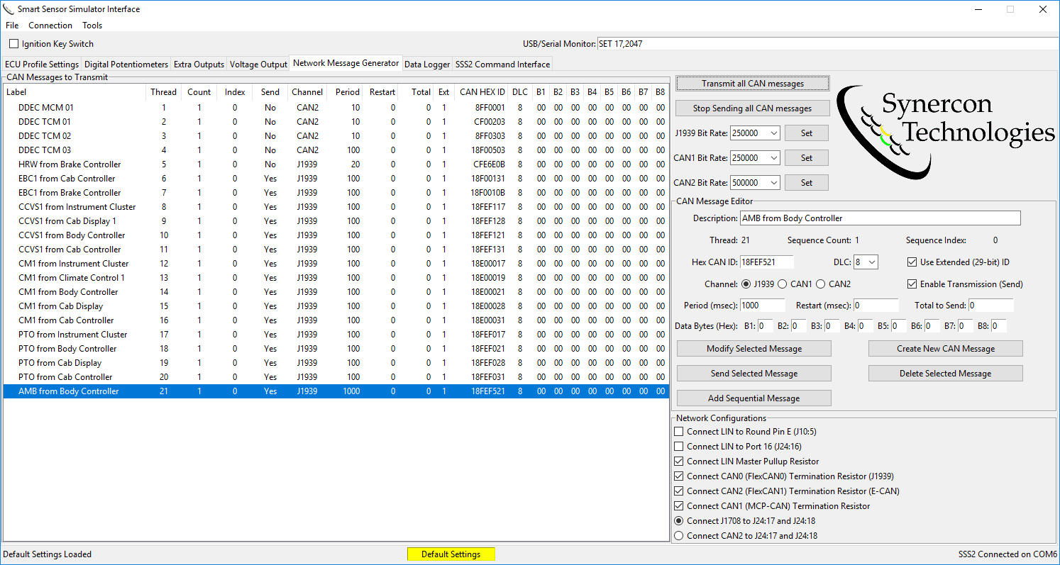
The Network Message Generator is a truly unique feature of the SSS2 and the Interface App. This tab controls the CAN messages that the SSS2 generates. These messages are important for an ECU to think it is in a truck and be fault free. The control over the CAN is down to the individual byte level, and working with this interface assumes the user has some experience and expertise with reading and writing CAN or J1939 messages. Some basic default J1939 messages are available by default and can be changed as needed.
In the CAN Messages to Transmit area the current list of messages that are available to be sent are listed. A mouse wheel will enable scrolling beyond the window. You can select a message and it will fill the CAN Message Editor area. If a message is selected, the edits done in the CAN Message Editor are automatically applied. For example, if byte B1 is changed, then as soon as the user presses Enter, Tab, or the Modify Selected Message button, that byte is updated in the SSS2 transmit queue.
CAN messages are only transmitted with the Ignition Key Switch is selected.
The button labeled “Transmit all CAN messages” puts a Yes in the send column for every message in the table and queues them up for transmission. Likewise, the button to stop sending messages will put a No in the Send column and command the SSS2 to cease sending messages out.
There are three CAN channels in the SSS2. Two of them are built into the Freescale K66 processor and use a library called FlexCAN. The third channel is implemented using a standalone chip that communicates to the processor with a SPI bus. This is a Microchip Technologies MCP2515 CAN controller. The three CAN channels enable multiple message channels for vehicles that have segregated networks. ECUs from Cummins and Detroit Diesel commonly use multiple CAN buses. Each of these channels can operate at a different baud rate. The dropdown menus select the rate, but to implement it in the system, the Set button aligned with the CAN channel must be pressed. The USB/Serial Monitor will confirm the baudrate for the selected CAN channel. CAN0 on the SSS2 corresponds to J1939. CAN1 on the SSS2 corresponds to CAN2, and MCPCAN on the SSS2 corresponds to CAN1. This has to do with the way the firmware and libraries in the SSS2 are written.
Many times ECUs will throw a fault code if a CAN or J1939 message is missing. Once the message is present, as indicated by its ID, the ECU is satisfies related to the network connectivity issues. As such, the message values may be irrelevant, so all zeros could be a satisfactory message for the ECU under investigation. If this is not the case, then manipulation of the individual bytes will be necessary.
Creating New CAN Messages
To create a new CAN message, select an existing message to act as a template. If you don’t have a template, then just pick a random message. Then press the button that says Create New CAN Message. A new dialog box will appear and ask you for a new name for the message. The choice is arbitrary, but a good pattern to follow is the Parameter Group Number acronym from the Source Address. Pressing OK will create a new message based on the message you had previously selected.
To come up with a desired hex CAN ID, you will need to know the Priority, Paraneter Group Number (PGN), Destination Address and Source Address for the message you want to send. It is highly recommended that you obtain a copy of the SAE J1939 Digital Annex to determine these values.
The data length code (DLC) is a number between 1 and 8 that indicates how many bytes are going to be transmitted. The data in the byte fields that are larger than the DLC will be ignored. Typically the DLC is 8 bytes, but some request messages only use 3 bytes.
The checkbox for the Extended ID is needed for J1939. If this box is not checked, then only 11 bits are used for the ID and any value over 0x7FF will be masked to 11 bits. In other words only the bottom 11 bits of the binary ID will be kept.
Message Sequences or Bursts
The ability for the SSS2 to simulate groups of messages is a very convenient feature when simulating connections to other devices that need to send more than 8 bytes at a time.
The spacing between messages is determined by the message Period in miliseconds. Each message in the group will be transmitted after the previous message with a time gap shown by the period. Once all the messages in the group are transmitted, the system waits for the Restart time to expire to start over. The Restart time starts with the first message. So, if the Restart time is less than the time it takes to broadcast all the messages in the group, then it will have no effect. This cycle will continue until the the number of messages is equal to the Total to Send. If the Total to Send is 0, then the system knows to ignore this and send messages continuously. These parameters give the user control over message burst timing.
Here is an example for sending a VIN over the network when the SSS2 is simulating Engine #2 on a vehicle.
This example shows the four messages needed to broadcast a VIN. Since a VIN is 17 characters, it requires more than one CAN frame. J1939-21 specifies how to do this using the Transport Protocol. There are two Parameter Group Numbers needed for the Transport Protocol. The first is the Connection Management (TP.CM), which has a value of 60416 (0x00EC00) and the second is the Data Transfer (TP.DT), which has a value of 60160 (0x00EB00).
The VIN parameter group number defined in J1939 is 65260 or 0x00FEEC. Typically VINs are 17 characters long. Let pretend to have a VIN of “123456789:;<=>?@A”, which are the sequential entries on the ASCII table from 0x31 to 0x41. We will send this three times spaced 5 seconds apart. The messages within the bursts will be 5 miliseconds apart. Since there are four messages per burst, we will need to send a total of 12 messages to get all three groups transmitted. We can verify this works by examining message traffic and observing the interpreted VIN in diagnostics software.
The output from this example in SocketCAN on Linux is shown with timespamps below. The messages were restarted once by pressing the Send Selected Message button to give a total of 24 entries.
ubuntu@arm:~$ candump -t a can1 |grep FF01
 (1502635909.905996) can1 18ECFF01 [8] 20 11 00 03 FF EC FE 00
 (1502635909.916053) can1 18EBFF01 [8] 01 31 32 33 34 35 36 00
 (1502635909.925980) can1 18EBFF01 [8] 02 38 39 3A 3B 3C 3D 3E
 (1502635909.936098) can1 18EBFF01 [8] 03 3F 40 41 FF FF FF FF
 (1502635914.906219) can1 18ECFF01 [8] 20 11 00 03 FF EC FE 00
 (1502635914.916206) can1 18EBFF01 [8] 01 31 32 33 34 35 36 00
 (1502635914.926206) can1 18EBFF01 [8] 02 38 39 3A 3B 3C 3D 3E
 (1502635914.936521) can1 18EBFF01 [8] 03 3F 40 41 FF FF FF FF
 (1502635919.906442) can1 18ECFF01 [8] 20 11 00 03 FF EC FE 00
 (1502635919.916430) can1 18EBFF01 [8] 01 31 32 33 34 35 36 00
 (1502635919.926436) can1 18EBFF01 [8] 02 38 39 3A 3B 3C 3D 3E
 (1502635919.936457) can1 18EBFF01 [8] 03 3F 40 41 FF FF FF FF
 (1502635966.983566) can1 18ECFF01 [8] 20 11 00 03 FF EC FE 00
 (1502635966.993553) can1 18EBFF01 [8] 01 31 32 33 34 35 36 00
 (1502635967.003521) can1 18EBFF01 [8] 02 38 39 3A 3B 3C 3D 3E
 (1502635967.013553) can1 18EBFF01 [8] 03 3F 40 41 FF FF FF FF
 (1502635971.983757) can1 18ECFF01 [8] 20 11 00 03 FF EC FE 00
 (1502635971.993747) can1 18EBFF01 [8] 01 31 32 33 34 35 36 00
 (1502635972.003742) can1 18EBFF01 [8] 02 38 39 3A 3B 3C 3D 3E
 (1502635972.013779) can1 18EBFF01 [8] 03 3F 40 41 FF FF FF FF
 (1502635976.983979) can1 18ECFF01 [8] 20 11 00 03 FF EC FE 00
 (1502635976.993966) can1 18EBFF01 [8] 01 31 32 33 34 35 36 00
 (1502635977.003967) can1 18EBFF01 [8] 02 38 39 3A 3B 3C 3D 3E
 (1502635977.013990) can1 18EBFF01 [8] 03 3F 40 41 FF FF FF FF
Data Logger Tab
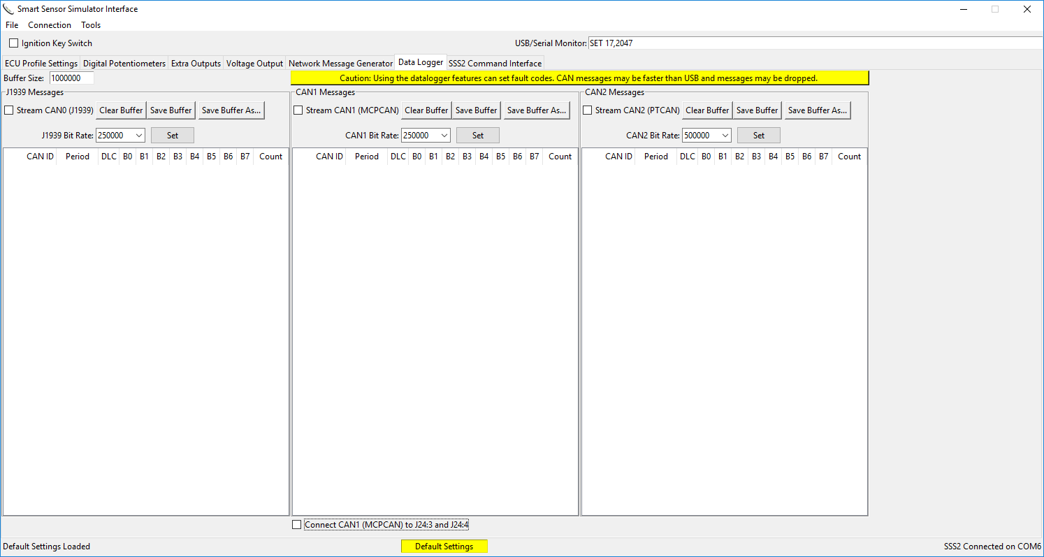
The data logger is a visual tool to identify the types and IDs of messages on the different CAN buses on the vehicle. The data from the different CANs are converted to a simple binary form and sent over the USB/Serial connection. The SSS2 Interface App gathers each of those messages and puts them into memory. It subsequently updates the table with the data. If the buffers are saved, the entire list is put into a comma separated values (CSV) table. Saving the buffer also clears it.
Data logging can be hard on the computing resources. It is possible to have more CAN traffic at one time than the USB system can handle. Use this a an exploratory tool only and do not use it during a forensic investigation.
SSS2 Command Interface Tab
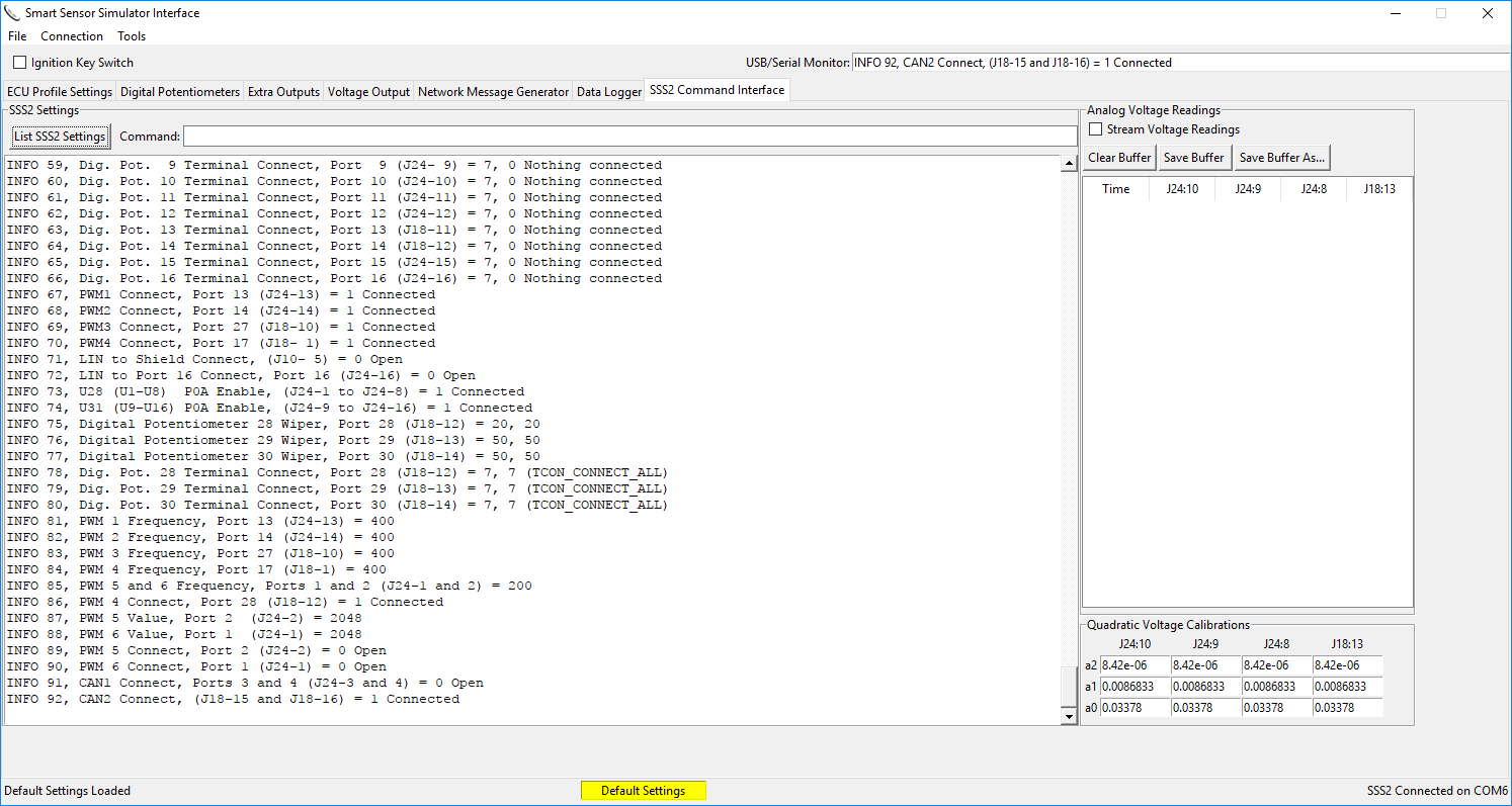
The command interface is like a custom serial terminal application. It enables the user to send serial commands to the SSS2 and see the response. A button to list all the settings is included that returns the current configuration of the SSS2. These settings are reflected in the other tabs. Also, the last line of the console window is present in the USB/Serial Monitor box in the upper right hand corner. The analog inputs are buffered and can read 12V signals. Samples are taken every tenth of a second.
There are four pins that can measure analog voltages. The calibrations for these readings are generic, but the user can tune those as necessary. Contact Synercon Technologies for more information on using the analog calibrations.

